


- Gain
- Noise Figure
- Linearity
- Maximum RF Input
Noise Figure Noise figure provides a measure of the noise contribution due to the LNA itself. In the picture below, the LNA amplifies both the signal and noise present at its input equally. In addition, the output includes noise due to the LNA. This in turn reduces the signal-to-noise ratio. A good LNA contributes very little noise to the overall picture.
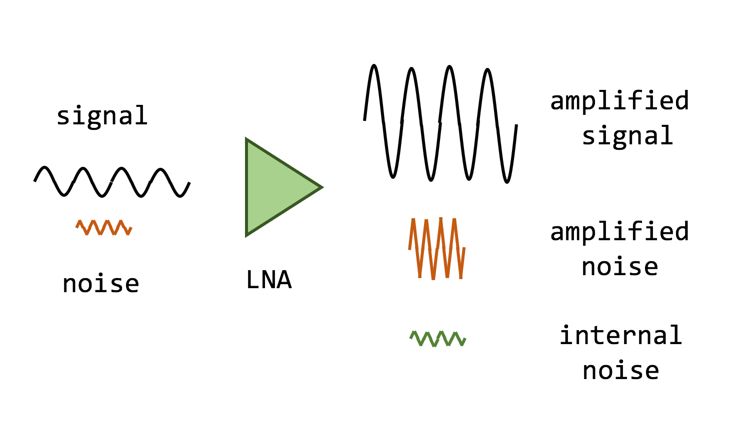 Low Noise Amplifiers Increase the Level of Both Input Signal and Noise Linearity The linearity of a LNA is a measure of its ability to amplify the signal without distortion. When a LNA is operating linearly, the output power in dB is the sum of the input signal and the gain. However, as the input signal level increases beyond a certain point, the output starts to level off, is no longer the sum of the input signal and gain. At this stage, the behavior of the LNA is no longer linear.
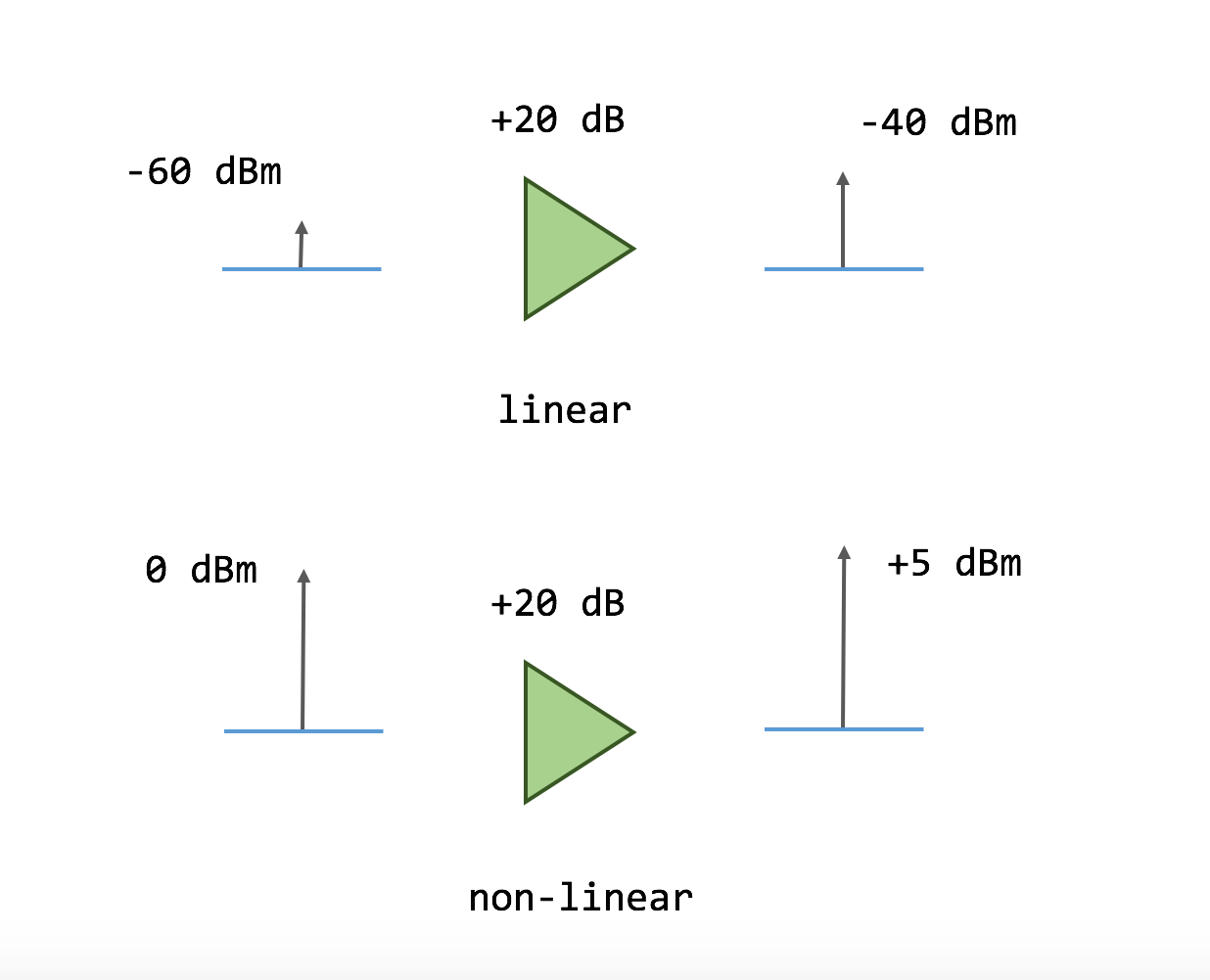
 In the picture below, the LNA is operating linearly when the signal present at its input has an amplitude of -60 dBm. However, as the input signal is increased to 0 dBm, the device is no longer linear, the output signal is distorted, the gain is no longer 20 dB and the output signal amplitude is only +5 dBm.
 Linearity of a Low Noise Amplifier Maximum RF Input Level This is simply the maximum signal level that a Low Noise Amplifier can tolerate. At this input signal level the LNA is deep into saturation and operation is non-linear. Some manufacturers specify a damage level which is the input signal level that can damage an amplifier. This quantity is most often specified in dBm.
 In addition to the above specifications, others that are important include Return Loss, DC operating voltage, current consumption and operating temperature.
The post An Introduction to Low Noise Amplifier Specifications appeared first on Software-Defined Radio Simplified.
Source: https://www.onesdr.com/2020/01/11/an-in ... fications/